
DIFFERENT TYPES OF DIESEL ENGINES | TWO-STROKE CYCLE ENGINE OPERATION
- NILESH GUPTA
- Jan 21, 2021
- 8 min read

1.9 DIFFERENT TYPES OF DIESEL ENGINES
A large number of diesel engine configurations and designs are in common
use. The largest marine and stationary power-generating diesels are two stroke
cycle engines and are discussed in the next section, 1.10. Small- and
medium-size diesel engines use the four-stroke cycle. Because air capacity is
an important constraint on the amount of fuel that can be burned in the diesel
engine, and therefore on power, turbocharging is used extensively. Larger
engines are almost always turbocharged. Small low-cost diesels are not
usually turbocharged. The details of the engine design also vary significantly
over the diesel size range. In particular, different combustion chamber
geometries and fuel-injection characteristics are required to deal effectively
with a major diesel engine design problem: achieving sufficiently rapid fuel air
mixing rates to complete the fuel-burning process in the short time
available. Smaller engines run at higher maximum speeds. Thus, a wide
variety of inlet port geometries, cylinder head and piston cavity or bowl
shapes, and fuel-injection patterns are used to achieve the airflows and fuel
flows needed to accomplish fast enough combustion over the diesel size
range.
Figure 1.31 shows a diesel engine typical of the heavy-duty truck
application. The design shown is a six-cylinder in-line engine. The drawing
indicates that diesel engines are generally substantially more rugged and
heavier than SI engines because stress levels are higher due to the
significantly higher pressure levels of the diesel cycle. The engine shown has
a displacement of 12.9 liters, a compression ratio of 16.5, and is
turbocharged. This type of diesel is called a direct-injection diesel since the
fuel is injected directly into a combustion chamber above the piston crown.
The combustion chamber shown is a “bowl-in-piston” design, which puts
most of the clearance volume into a compact cavity in the piston crown. With
this type of diesel engine, it is often necessary to use a swirling airflow
rotating about the cylinder axis, which is created by suitable design of the
inlet port and valve, to achieve fast enough fuel-air mixing and fuel-burning
rates. The fuel injector, shown on the cylinder axis in the drawing, has a
multihole nozzle. It typically has four to six holes in this application. The fuel
jets move out radially from the nozzle holes close to the center of the piston
bowl into the (swirling) airflow. Figure 1.31 Six-cylinder 12.9-liter turbocharged direct-injection truck diesel engine: transverse and longitudinal sections. Bore 135 mm, stroke 150
mm, compression ratio 16:1, governed speed 2100 rev/min, maximum output
294 kW, maximum torque 1667 N · m at 1300 rev/min.
Figure 1.32 shows a 2.2-liter four-cylinder high-speed direct-injection
(HSDI) diesel is typical of those used in automobiles. It has four valves per
cylinder, with the fuel injector and bowl-in-piston combustion chamber
centered on each cylinder axis. These types of engines are highly boosted to
give high torque at low- to mid-engine speeds per unit displaced cylinder
volume. The compressor exit air, cooled in a heat exchanger, enters the
cylinder via intake ports that generate swirl about the cylinder axis. During
the compression stroke, the flow of this swirling air into the reentrant bowlin-
piston significantly enhances the swirl, thereby achieving high rates of
mixing of air with the injected fuel sprays close to the top center. Maximum rated
speeds (4500 to 5000 rev/min) are lower than maximum speeds of gasoline
SI engines due to fuel-air mixing rate limitations. The compression ratio of
these HSDI engines is 18 to 20:1, somewhat above the value that gives
maximum engine efficiency. This is done to obtain higher air compression
temperatures to enable cold engines starting at low cranking speeds. An
electrically heated ceramic glow plug is usually inserted through the cylinder
head in these size engines to assist the cold starting process.
Figure 1.32 Small 2.2-liter four-cylinder high-speed direct-injection
automobile diesel engine: maximum power 93 kW; maximum torque 285 N ·
m at 1750 rev/min; maximum boost 0.9 bar (gauge); compression ratio 18.5.
The smallest diesels operate at higher engine speeds than do larger
engines: hence the time available for burning the fuel is less and the fuel injection
and combustion systems must achieve faster fuel-air mixing rates.
Figure 1.32 shows how this rapid combustion is realized in HSDI diesels.
Historically, in the smallest sizes diesel engines, this can be accomplished by
using an indirect-injection or prechamber type of diesel. Fuel is injected into
an auxiliary combustion chamber that is separated from the main combustion
chamber above the piston by a passageway or nozzle. During the latter stages
of the compression process, air is forced through this nozzle from the
cylinder into the prechamber at high velocity. Fuel is injected into the highly
turbulent and often rapidly swirling flow in this prechamber, and very high
fuel-air mixing rates are achieved. Combustion starts in the prechamber, and
the resulting pressure rise in the prechamber forces burning gases, fuel, and
air into the main chamber. Since this outflow is also extremely vigorous,
rapid mixing then occurs in the main chamber as the burning jet exiting the
prechamber mixes with the remaining air and combustion is completed. A
glow plug is also shown in the auxiliary chamber; this plug is electrically
heated during cold engine start-up to raise the temperature of the air charge
and the fuel sufficiently to achieve autoignition. The compression ratio of this
the engine is high—around 20. Indirect-injection diesel engines require higher
compression ratios than direct-injection engines to start adequately when
cold.
1.10 TWO-STROKE CYCLE ENGINE OPERATION
The two-stroke engine is used at the small-size and very large-size ends of
the engine market. In small sizes, the two-stroke cycle SI engine is cheap,
compact and light, simple, and robust. This is the basis of its market appeal
in mopeds, scooters, motorcycles, and snowmobiles, in portable devices
such as chain-saws and brushcutters, in agricultural and construction devices
such as lawn mowers, disc saws, and snow blowers, in the outboard marine
engine arena, and in light and in remotely piloted aircraft. The very large
diesel engines used in marine and power-generation applications are also
two-stroke cycle engines. These large internal combustion engines are the
most efficient and cost effective prime movers currently available. The two stroke
diesel has also been used in the locomotive and in parts of the truck
market. 29,30 The passenger-car and truck engine markets are now, however,
dominated by four-stroke cycle engines. Key operating features of the two-stroke cycle
are its power stroke every crankshaft revolution and its scavenging of the burned gases from the engine cylinder with fresh charge. Doubling the number of power strokes per unit
time relative to the four-stroke cycle increases the power output per unit
displaced volume. It does not, however, increase by a factor of two. The
outputs of two-stroke engines range from only 20% to 60% above those of
equivalent-size four-stroke units. This lower increase in practice is a result
of the poorer than ideal charging efficiency, that is, incomplete filling of the
cylinder volume with fresh air due to incomplete scavenging of the residual
burned gases. Doubling the number of power strokes per unit time also
halves the intervals between combustion-generated pressure impulses. This
results in a smoother crankshaft torque versus time profile.
The two-stroke cycle’s process of scavenging the burned gases from the
engine cylinder with fresh charge—its gas exchange process—has several
consequences. First, charging losses are inevitable. Under higher load
conditions, in a typical small two-stroke engine, some 20% or more of the
fresh charge that enters the cylinder is lost due to short-circuiting to the
exhaust. When the fuel is mixed with air prior to cylinder entry, this process
results in very high hydrocarbon emissions and poor fuel consumption
compared with the four-stroke cycle engine. However, as both exhaust and
charging occur around BC, the exhaust and intake ports can be situated near
the bottom end of the cylinder and can be covered and uncovered by a long skirt
piston (see Fig. 1.33). This simple geometric two-stroke cycle
configuration obviates the need for valves and their actuating gear. It also
substantially simplifies the engine structure and the production process, and
significantly reduces engine cost.
Figure 1.33 Cylinder-pressure versus cylinder-volume trace for a two stroke
cycle engine cylinder. Exhaust and transfer or scavenge ports are
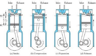
uncovered by the piston as shown. In the two-stroke engine cycle, the compression, combustion, and expansion processes are similar to the equivalent four-stroke cycle
processes; it is the intake and exhaust processes that are different ( Fig.
1.33). The sequence of events in a port-scavenged two-stroke engine is
illustrated in
Fig. 1.34. In such engines, both exhaust and the scavenging (or
transfer) ports are at the same end of the cylinder and are uncovered as the
piston approaches BC ( Fig. 1.34). After the exhaust ports open, the cylinder
pressure falls rapidly as burned gases flow out of the cylinder into the
exhaust system, in a blowdown process as shown. The scavenging or transfer
ports then open, and once the cylinder pressure p falls below the scavenging
pressure pi, fresh charge flows into the cylinder. Burned gases, displaced by
this fresh charge, continue to flow out of the exhaust port (along with some of
the fresh charge). Once the ports close as the piston starts the compression
stroke, compression, fuel-injection and fuel-air mixing in direct-injection
engines, combustion, and expansion processes proceed as in the equivalent
four-stroke engine cycle. 29, 30 (Fresh charge is fuel vapor and air in engines
where fuel and air are “premixed” before entry into the cylinder: the fresh
charge is air if direct fuel injection is used.) Figure 1.34 Sequence of events during expansion, gas exchange, and
compression processes in a loop-scavenged two-stroke cycle compression ignition
engine. Cylinder volume/clearance volume V/Vc, cylinder pressure
p, exhaust port open area Ae, and intake port open area Ai are plotted against
crank angle.
Figure 1.35 shows how this two-stroke cycle is realized in a small
gasoline engine.
This is an experimental single-cylinder crankcase scavenged
engine, with a pneumatic direct fuel injection system to avoid high
hydrocarbon emissions and achieve good fuel consumption. Air flows into
the crankcase, through Reed valves, as the piston travels up the cylinder. This
air is compressed as the piston travels down. Air flows into the cylinder
once the transfer or scavenging ports, which connect the crankcase to the
cylinder, are uncovered. Fuel is injected after the transfer ports have been
closed off. This engine employs a novel combustion approach—often called
activated radical combustion. By retaining the appropriate amount of burned
residual gas within the cylinder by restricting the flow out of the exhaust
ports with a throttle valve, the in-cylinder unburned gas temperature at the
the end of compression can be raised and controlled. This in-cylinder mixture
can then be made to autoignition at the appropriate point in the cycle—at the
end of compression, just before TC. This spontaneous autoignition of the
complete well-mixed fuel vapor, air, and burned residual in-cylinder charge
is an alternative combustion process to the standard spark-ignited or diesel
combustion processes. It is often called homogeneous charge compression
ignition (HCCI) or controlled autoignition (CAI). This HCCI combustion
the concept is also being developed for four-stroke cycle engines. At high
outputs, when effective scavenging of the burned gases becomes important,
this two-stroke cycle engine reverts to the normal spark-ignition engine flame
propagation process.
Figure 1.35 Honda experimental two-stroke cycle loop-scavenged engine
with pneumatic direct in-cylinder fuel injection, employing an activated
radical combustion process—controlled autoignition of the in-cylinder fuel vapor,
air, burned residual mixture just before top center. 402 cm 3
displacement, bore and stroke 80 mm, trapped compression ratio 6:1.
Generates 33 kW at 6900 rev/min
Diesels, in the very large size engines, used for marine propulsion and
electrical power generation, also operate using the two-stroke cycle. Figure
1.36 shows such a two-stroke cycle marine engine, available with 4 to 12
cylinders, with a maximum bore of 0.6 to 0.9 m and stroke of 2 to 3 m, which
operates at speeds of about 100 rev/min. These engines are normally of the
crosshead type shown to reduce piston side forces on the cylinder. The gas exchange process is initiated by opening the exhaust valve in the cylinder
head, followed by the piston uncovering the transfer ports at the lower end of
the cylinder liner. The expanding exhaust gases leave the cylinder via the
exhaust valve and manifold, and pass through the turbocharger turbine.
Compressed air enters the cylinder via the transfer ports, continuing the
scavenging process; the air is supplied from the turbocharger compressor and
intercooler. At part load, electrically driven blowers cut in to compress the
scavenge air. Because these large engines operate at low speed, the motion
induced by the injected fuel jets is sufficient to mix the fuel with air and burn
it in the time available. Thus, a simple open combustion chamber shape can
be used, which achieves efficient combustion even with the low-quality
heavy fuels used with these types of engines. The pistons are water cooled in
these very large engines. The splash or jetted oil piston cooling used in
small- and medium-size diesels is not adequate. Figure 1.36 Cross-section of an
IHI-Sulzer uniflow-scavenged large two stroke
cycle turbocharged diesel engine, developing 1590 kW per cylinder at
127 rev/min. Stroke to bore ratio about 2:5.


Comments