
ENGINE OPERATING CYCLES | ENGINE COMPONENTS
- NILESH GUPTA
- Jan 20, 2021
- 7 min read

Updated: Jan 21, 2021
1.3 ENGINE OPERATING CYCLES
Most of this is about reciprocating engines, where each piston moves
back and forth in a cylinder and transmits power from the high-pressure and
temperature burned gases inside the cylinder through the piston and the
connecting rod and crank mechanism to the drive shaft as shown in Fig. 1.1.
The rotation of the crank produces a cyclical piston motion. The piston
comes to rest at the top-center (TC) crank position and bottom-center (BC)
crank position when the cylinder volume is a minimum or maximum,
respectively. d The minimum cylinder volume is called the clearance volume
Vc. The volume swept out by the piston, the difference between the maximum
or total volume Vt and the clearance volume, is called the displaced or swept
volume Vd. The ratio of maximum volume to minimum volume is the
compression ratio rc. Values of rc are 8 to 12 for SI engines and typically in
the ranges of 14 to 22 for CI engines.
Basic geometry of the reciprocating internal combustion engine.
Figure 1.1 Basic geometry of the reciprocating internal combustion engine.
V c , Vd, and Vt indicate clearance, displaced, and total cylinder volumes.
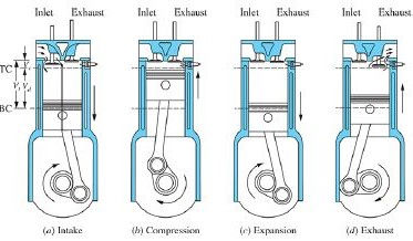
The majority of reciprocating engines operate on what is known as the
four-stroke cycle. Each cylinder requires four strokes of its piston—two
revolutions of the crankshaft—to complete the sequence of events that
produces one power stroke. Both SI and CI engines use this cycle that
comprises
The four-stroke operating cycle
Figure 1.2 The four-stroke operating cycle
1. An intake stroke, which starts with the piston at TC and ends with
the piston at BC, which draws fresh air or fuel-air mixture into the
cylinder. To increase the mass inducted, the inlet valve opens shortly
before the stroke starts and closes after it ends.
2. A compression stroke, which starts with the piston at BC and ends at
TC, when the mixture inside the cylinder is compressed to a small
fraction of its initial volume. Toward the end of the compression
stroke, combustion is initiated and the cylinder pressure rises more
rapidly.
3. A power stroke, or expansion stroke, which starts with the piston at
TC and ends at BC as the high-temperature, high-pressure gases push
the piston down and force the crank to rotate. About five times as
much work is done on the piston during the power stroke as the piston
had to do during compression. As the piston approaches BC, the
exhaust valve opens to initiate the exhaust process and drop the
cylinder pressure to close to the exhaust system pressure.
4. An exhaust stroke, where, as the piston moves from BC to TC, the
remaining burned gases exit the cylinder: first, because the cylinder
pressure may be significantly higher than the exhaust pressure; then as
these gases are swept out by the piston as it moves toward TC. As the
piston approaches TC the inlet valve opens and just after TC the
exhaust valve closes. The cycle then starts again.
Though often called the Otto cycle after its inventor, Nicolaus Otto, who
built the first engine operating on these principles in 1876, the more
descriptive four-stroke nomenclature is preferred.
Simplest types of two-stroke engine designs.
The four-stroke cycle requires, for each engine cylinder, two crankshaft
revolutions for each power stroke. To obtain a higher power output from a
given engine size, and a simpler valve design, the two-stroke cycle was
developed. The two-stroke cycle is applicable to both SI and CI engines.
Figure 1.3 shows one of the simplest types of two-stroke engine designs.
Ports in the cylinder liner, opened and closed by the piston motion, control
the exhaust flow out of the cylinder and the fresh charge flow into the
cylinder, while the piston is close to BC. The two strokes are:
Figure 1.3 The two-stroke operating cycle. A crankcase-scavenged engine
is shown.1. A compression stroke, which starts with the closing of the fresh
charge transfer ports and then the exhaust ports, and compresses the
cylinder contents as the piston moves up the cylinder, and also draws
fresh charge into the crankcase through the inlet Reed valve. As the
piston approaches TC, combustion is initiated.
2. A power or expansion stroke, similar to that in the four-stroke cycle
until the piston approaches BC, when first the exhaust ports and then
the transfer ports are uncovered ( Fig. 1.3). Most of the burnt gases
exit the cylinder in an exhaust blowdown process. When the transfer
ports are uncovered, the fresh charge that has been compressed in the
crankcase flows into the cylinder. The piston and the ports are
generally shaped to deflect the incoming charge from flowing directly
into the exhaust ports, and to achieve effective scavenging of the
residual in-cylinder burned gases by this fresh charge.
Each engine cycle with one power stroke is completed in one crankshaft
revolution. However, it is difficult to fill completely the displaced volume
with fresh charge, and some of the fresh mixture flows directly out of the
cylinder during the scavenging process. e The example shown is a crossscavenged
design; other approaches use loop-scavenging or uniflow gas
exchange processes
1.4 ENGINE COMPONENTS
Cutaway drawings of a four-stroke spark-ignition (SI) engine and a diesel
(CI) engine are shown in Figs. 1.4 and 1.5, respectively. The SI engine is a
four-cylinder in-line automobile engine. The major components are labeled.
The diesel is a six-cylinder in-line heavy-duty truck engine. The function of
the major components of these engines and their construction materials will
now be reviewed.
Figure 1.4 Cutaway drawing of 2.2-liter displacement four-cylinder sparkignition
engine. Bore 87.5 mm, stroke 92 mm,
compression ratio 8.9.
Figure 1.5 Cross-section drawing of a four-stroke cycle 6.7-liter in-line
six-cylinder turbocharged diesel engine. Bore 107 mm, stroke 124 mm,
compression ratio 17.3, maximum torque 1200 N · m at 1600 rev/min,
maximum power 285 kW at 2800 rev/min. ( Courtesy Cummins Engines.)
The engine cylinders are contained in the engine block.
The block has
traditionally been made of gray cast iron because of its good wear resistance
and low cost, but is often now made of aluminum. Passages for the cooling
water is cast into the block. Heavy-duty and truck engines often use
removable cylinder sleeves pressed into the block that can be replaced when
worn. These are called wet liners or dry liners depending on whether the
sleeve is in direct contact with the cooling water. Aluminum is used in
automotive SI engine blocks to reduce engine weight. Iron cylinder liners
may be inserted at the casting stage, or later on in the machining and
assembly process. The crankcase is often integral with the cylinder block.
The crankshaft has traditionally been a steel forging; nodular cast iron
crankshafts are also accepted practice in automotive engines. The crankshaft is supported in main bearings. The number of crankshaft bearings depends
largely on the engine’s loading and maximum speed. The maximum number of
main bearings is one more than the number of cylinders; there may be less.
The crank has eccentric portions (crank throws); the connecting rod big-end
bearings attach to the crank pin on each throw. Both main and connecting rod
bearings use steel-backed precision inserts with bronze, babbitt, or aluminum
as the bearing materials. The crankcase is sealed at the bottom with a
pressed-steel or cast aluminum oil pan, which acts as an oil reservoir for the
lubricating system.
Pistons are made of aluminum in smaller engines or cast iron in larger
slower-speed engines. The piston both seals the cylinder and transmits the
combustion-generated gas pressure to the crank pin via the connecting rod.
The connecting rod, usually a steel or alloy forging (though sometimes
aluminum), is fastened to the piston by means of a steel piston pin through the
rod upper end. The piston pin is usually hollow to reduce its weight.
The oscillating motion of the connecting rod exerts an oscillating force on
the cylinder walls via the piston skirt (the region below the piston rings). The
a piston skirt is usually shaped to provide appropriate thrust surfaces. The
piston is fitted with rings that ride in grooves cut in the piston head to seal
against gas leakage and control oil flow. The upper ring is the compression
ring that is forced outward against the cylinder wall and downward onto the
groove face. The lower rings scrape the surplus oil from the cylinder wall to
reduce exposure to the hot burned gases, and return it to the crankcase. The
crankcase must be ventilated to remove gases that blow by the piston rings,
to prevent pressure buildup. The crankcase gases are recycled to the engine
intake.
The cylinder head (or heads in V engines) seals off the cylinders and is
made of aluminum or cast iron. It must be strong and rigid to distribute the
gas forces acting on the head as uniformly as possible through the engine
block. The cylinder head contains the spark plug (for an SI engine) or fuel
injector (for a CI or direct-injection engine), and, in overhead valve engines,
parts of the valve mechanism.
The valves shown in Fig. 1.4 are poppet valves, the valve type normally
used in four-stroke engines. The engine shown has one intake and one exhaust
valve: most modern engines have four valves per cylinder (two intake and
two exhaust valves), or three valves (two intake and one exhaust). Valves are
made from forged alloy steel; the cooling of the exhaust valve, which
operates at up to about 700°C, may be enhanced by using a hollow stem
partially filled with sodium, which through evaporation and condensation
carries heat from the hot valve head to the cooler stem. Most modern SI
engines have overhead valve locations (sometimes called valve-in-head or Ahead
configurations) as shown in Fig. 1.4. This geometry leads to a compact
combustion chamber with minimum heat losses and flame travel time, and
improves the breathing capacity. Older geometries such as the L head where
valves are to one side of the cylinder are now only used in small low-cost
engines.
The valve stem moves in a valve guide, which can be an integral part of
the cylinder head (or engine block for L-head engines), or may be a separate
unit pressed into the head (or block). The valve seats may be cut in the head
or block metal (if cast iron) or hard steel inserts may be pressed into the
head or block. A valve spring, attached to the valve stem with a spring
washer and split keeper, holds the valve closed. A valve rotator turns the
valves a few degrees on opening to wipe the valve seat, avoid local hot
spots, and prevent deposits building up in the valve guide.
A camshaft made of cast iron or forged steel with one cam per valve (or
pair of valves in four valves per cylinder engines) is used to open and close
the valves. The cam surfaces are hardened to obtain adequate life. In fourstroke
cycle engines, camshafts turn at one-half the crankshaft speed.
Mechanical or hydraulic lifters or tappets slide in the block and ride or roll
on the cam. Depending on valve and camshaft location, additional members
are required to transmit the tappet motion to the valve stem; for example, in
in-head valve engines with the camshaft at the side, a pushrod and rocker
arms are used. A trend in high-speed automotive engines is to mount the
camshaft over the head with the cams acting either directly or through a
pivoted follower on the valve. Also, variable control of valve opening and
closing as a function of engine operating conditions, in its simplest form
using a camshaft phasing device, is replacing fixed valve timing engine
designs. Camshafts are gear, belt, or chain driven from the crankshaft.
An intake manifold (aluminum, cast iron, or plastic) and an exhaust
manifold (generally of cast iron) complete the SI engine assembly. Other
engine components specific to SI engines—fuel injectors, ignition systems—
are described in more detail in the remaining sections in this chapter.
The four-stroke cycle diesel engine shown in Fig. 1.5 is an in-line six cylinder
design commonly used for large trucks. The engine is turbocharged
to increase the amount of air that enters the cylinder each cycle. The
turbocharger consists of a centrifugal compressor (which compresses the air
prior to entry into the cylinder on the same shaft as the exhaust-gas-driven
turbine that powers the compressor). In diesel engines, the fuel injectors are
mounted in the cylinder head. Diesel fuel-injection systems are discussed in
more detail in


Comments