
INTRODUCTION AND HISTORICAL PERSPECTIVE | ENGINE CLASSIFICATIONS
- NILESH GUPTA
- Jan 19, 2021
- 11 min read

Updated: Jan 21, 2021
1.1 INTRODUCTION AND HISTORICAL
PERSPECTIVE
The purpose of internal combustion engines is to produce mechanical power
from the chemical energy contained in the fuel. In internal combustion
engines, as distinct from external combustion engines, this energy is released
by burning or oxidizing the fuel inside the engine. The fuel-air mixture before
combustion and the burned products after combustion are the actual working
fluids. The work transfers that provide the desired power output occur
directly between these working fluids and the mechanical components of the
engine. The internal combustion engines that are the subject of this book are
spark-ignition (SI) engines (sometimes called Otto engines, or gasoline or
petrol engines, though other fuels can be used) and compression-ignition (CI)
or diesel engines. a Because of their simplicity, ruggedness, high power to
weight ratio, efficiency, and low cost, these two types of engine have found
wide application in transportation (land, sea, and air) and power generation.
It is the fact that combustion takes place inside the work-producing part of
these engines that makes their design and operating characteristics
fundamentally different from those of other types of engine.
Power-producing engines have served human beings for over two and a
half centuries. For the first 150 years, water, converted to steam, was
interposed between the combustion gases produced by burning the fuel and
the work-producing piston-in-cylinder expander. It was not until the 1860s
that the internal combustion engine became a practical reality. 1, 2 The early
engines developed for commercial use burned coal-gas air mixtures at
atmospheric pressure—there was no compression before combustion. J. J. E.
Lenoir (1822–1900) developed the first marketable engine of this type. Gas
and air was drawn into the cylinder during the first half of the piston stroke.
The charge was then ignited with a spark, the pressure increased, and the
burned gases then delivered power to the piston for the second half of the
stroke. The cycle was completed with an exhaust stroke. Some 5000 of these
engines were built between 1860 and 1865 in sizes up to six horsepower.
Efficiency was at best about 5%.
A more successful development—an atmospheric engine introduced in
1867 by Nicolaus A. Otto (1832–1891) and Eugen Langen (1833–1895)—
used the pressure rise resulting from combustion of the fuel-air charge early
in the outward stroke to accelerate a free piston and rack assembly so its
momentum would generate a vacuum in the cylinder. Atmospheric pressure
then pushed the piston inward, with the rack engaged through a roller clutch
to the output shaft. Production engines, of which about 5000 were built,
obtained thermal efficiencies of up to 11%. A slide valve controlled intake,
ignition by a gas flame, and exhaust.
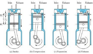
To overcome this engine’s shortcomings of low thermal efficiency and
excessive size and weight, Otto proposed an engine cycle with four piston
strokes: an intake stroke, then a compression stroke before ignition, an
expansion or power stroke where work was delivered to the crankshaft, and
finally an exhaust stroke. He also proposed incorporating a stratified-charge
induction system, though this was not achieved in practice. His prototype
the four-stroke engine first ran in 1876. A comparison between the Otto engine
and its atmospheric-type predecessor indicates the reason for its success (
Table 1.1): the enormous reduction in engine weight and volume. This was
the breakthrough that effectively founded the internal combustion engine
industry. By 1890, almost 50,000 of these engines had been sold in Europe
and the United States.
Comparison of Otto’s early four-stroke cycle and Otto-Langen’s engines
In 1884, an unpublished French patent issued in 1862 to Alphonse Beaude
Rochas (1815–1893) was found that described the principles of the four stroke
cycle. This chance discovery cast doubt on the validity of Otto’s own
patent for this concept, and in Germany, it was declared invalid. Beau de
Rochas also outlined the conditions under which maximum performance and
efficiency in an internal combustion engine could be achieved. These were:
1. The largest possible cylinder volume with the minimum boundary
surface
2. The greatest possible working speed
3. The greatest possible expansion ratio
4. The greatest possible pressure at the beginning of expansion
The first condition holds heat losses from the charge to a minimum. The
the second condition increases the power output from a given size engine. The
third condition recognizes that the greater the expansion of the
post combustion gases, the greater the amount of work extracted. The fourth
condition recognizes that higher initial pressures make greater expansion
possible and give higher pressures throughout the process, both resulting in
greater work transfer. Although Beau de Rochas’ unpublished writings
predate Otto’s developments, he never reduced these ideas to practice. Thus
Otto, in the broader sense, was the inventor of the modern internal
combustion engine as we know it today.
Further developments followed fast once the full impact of what Otto had
achieved became apparent. By the 1880s, several engineers (e.g., Dugald
Clerk, 1854–1913, James Robson, 1833–1913, in England, and Karl Benz,
1844–1929, in Germany) had successfully developed two-stroke cycle
internal combustion engines where the exhaust and intake processes occur
during the end of the power stroke and the beginning of the compression
stroke. James Atkinson (1846–1914) in England made an engine with a
longer expansion than compression stroke, which had a high efficiency for
the times but mechanical weaknesses. It was recognized that efficiency was a
direct function of expansion ratio, yet compression ratios were limited to
less than four if serious knock problems were to be avoided with the
available fuels. Substantial carburetor and ignition system developments
were required, and occurred, before high-speed gasoline engines suitable for
automobiles became available in the late 1880s. Stationary engine progress
also continued. By the late 1890s, large single-cylinder engines of 1.3-m
a bore fueled by low-energy blast furnace gas produced 600 bhp at 90 rev/min.
In Britain, legal restrictions on volatile fuels turned their engine builders
toward kerosene. Low compression ratio “oil” engines with heated external
fuel vaporizers and electronic ignition were developed with efficiencies
comparable with those of gas engines (14 to 18%). The Hornsby-Ackroyd
engine became the most popular oil engine in Britain, and was also built in
large numbers in the United States. 2
In 1892, the German engineer Rudolf Diesel (1858–1913) outlined in his
patent a new form of internal combustion engine. His concept of initiating
combustion by injecting a liquid fuel into the high-temperature air in the
cylinder produced by compression permitted a doubling of efficiency over
the other internal combustion engines then available. Much greater
compression and expansion ratios, without detonation or knock, were now
possible. However, even with the efforts of Diesel and the resources of
M.A.N. in Augsburg combined, it took 5 years to develop a practical engine.
Engine developments, perhaps less fundamental but nonetheless important
to the steadily widening internal combustion engine markets, have continued
ever since. 2-4 There has always been an interest in engine geometries
different from the standard reciprocating piston-in-cylinder, connecting rod,
and crankshaft arrangement. Especially, there has been an interest in rotary
internal combustion engines. Although a wide variety of experimental rotary
engines have been proposed over the years, 5 the first practical rotary
internal combustion engine, the Wankel, was not successfully tested until
1957. That engine, which evolved through many years of research and
development, was based on the designs of the German inventor Felix Wankel.
6, 7 While the Wankel engine has been used in niche markets, its advantages of
compactness and smoother operation have not been sufficient to overcome its
high manufacturing cost.
Fuels have also had a major impact on engine development. The earliest
engines used for generating mechanical power burned gaseous fuels.
Gasoline, and lighter fractions of crude oil, became available in the late
1800s, and various types of carburetors were developed to vaporize the fuel
and mix it with air. Before about 1905, there were few issues with gasoline;
though compression ratios had to be low (4 or less) to avoid knock, the
highly volatile fuel made starting easy and gave good cold weather
performance. However, a serious crude oil shortage developed, and to meet
the fivefold increase in gasoline demand between 1907 and 1915, the yield
from crude had to be raised. Through the work of William Burton (1865–
1954) and his associates of Standard Oil of Indiana, a thermal cracking
process was developed whereby heavier oils were heated under pressure
and decomposed into less complex, more volatile compounds. These
thermally cracked gasolines satisfied demand, but their higher boiling point
range created cold weather starting problems. Fortunately, electrically driven
starters, introduced in 1912, came along just in time.
On the farm, kerosene was the logical fuel for internal combustion engines
since it was used for heat and light. Many early farm engines had heated
carburetors or vaporizers to enable them to operate with such a fuel.
The period following World War I saw a tremendous advance in our
understanding of how fuels affect combustion, and especially the problem of
knock. The antiknock effect of tetraethyl lead was discovered at General
Motors, 4 and it became commercially available as a gasoline additive in the
United States in 1923. In the late 1930s, Eugene Houdry found that vaporized
oils passed over an activated catalyst at 450 to 480°C were converted to
high-quality gasoline in much higher yields than was possible with thermal
cracking. These advances, and others, permitted fuels with ever better
antiknock properties to be produced in large quantities; thus engine
compression ratios steadily increased, improving power and efficiency.
During the past several decades, new factors for change have become
important and now significantly affect engine design and operation. These
factors are, first, the need to control the automotive contribution to urban air
pollution and, second, the need to achieve significant improvements in
automotive fuel consumption.
The automotive air-pollution problem became apparent in the 1940s in the
Los Angeles basin. In 1952, it was demonstrated by Prof. A. J. Haagen-Smit
that the smog problem there resulted from reactions between oxides of
nitrogen and hydrocarbon compounds in the presence of sunlight. 8 In due
course it became clear that the automobile was a major contributor to
hydrocarbon and oxides of nitrogen emissions, as well as the prime cause of
high carbon monoxide levels in urban areas. Diesel engines are a significant
source of small soot or smoke particles, as well as hydrocarbons and oxides
of nitrogen. Table 1.2 outlines the dimensions of the problem. As a result of
these developments, emission standards for automobiles were introduced
first in California, then nationwide in the United States, starting in the 1960s.
Emission standards in Japan and Europe, and for other engine applications,
have followed. Substantial reductions in emissions from spark-ignition and
diesel engines have been achieved. Both the use of catalysts in SI engine
exhaust systems for emissions control and concern over the toxicity of lead
antiknock additives have resulted in the reappearance of unleaded gasoline
as the dominant part of the automotive fuels market. These emission-control
requirements and fuel developments have produced significant changes in the
way internal combustion engines are now designed and operated.
The automotive urban air-pollution problem: typical vehicle emissions
Internal combustion engines are also an important source of noise.
There are several sources of engine noise: the exhaust system, the intake system, the
fan used for cooling, and the engine block surface. The noise may be
generated by aerodynamic effects, may be due to forces that result from the
combustion process, or may result from mechanical excitation by rotating or
reciprocating engine components. Vehicle noise legislation to reduce this
impact on the ambient environment (and thus on people) was first introduced
in the early 1970s.
During the 1970s, the price of crude petroleum rose rapidly to several
times its cost (in real terms) in 1970. In the 1980s, the price of crude oil fell,
and then fluctuated at relatively low levels until the early 2000s when it rose
too close to its late 1970s values. The price then fell rapidly, and then rose
again. Currently, the growth in oil demand in the developing world, the
uncertainty in future extraction from established fields and discovery of new
sources of oil, and the nonuniform concentration of petroleum reserves in a
few nations, suggest that the balance between global oil production and
transportation fuel demand will be tight over the next few decades. This
uncertainty regarding the longer-term availability of adequate supplies of
petroleum-based fuels is creating substantial pressures for significant
improvements in internal combustion engine efficiency (in all the engine’s
many applications). Much work is being done to develop the supply and use
of alternative fuels to gasoline and diesel. Of the non petroleum-based fuels,
natural gas, methanol (methyl alcohol), and biomass-derived fuels such as
ethanol (ethyl alcohol) and biodiesel are receiving significant attention.
Synthetic gasoline and diesel are being made from tar (oil) sands, and could
be produced from shale oil or coal. Hydrogen is being considered as a
longer-term zero carbon containing possibility.
The growing consumption of fossil fuels has raised the concern that the
greenhouse gas (GHG) emissions from our energy supply and use are causing
global warming that could lead to changes in our climate. Emissions of
carbon dioxide, along with other GHGs—methane, nitrous oxide, three
groups of fluorinated gases (sulfur hexafluoride, hydrofluorocarbons, and
perfluorocarbons), ozone—will need to be significantly reduced over the
next several decades. Thus, internal combustion engines will need to become
more efficient, and low GHG emitting sources of energy will need to be
developed so that consumption of petroleum-based fuels—gasoline and
diesel—can be significantly reduced. Transportation is estimated to be the
source of about one-quarter of the world’s GHG emissions.
Table 1.3 lists the CO2 emissions of various fuels and other sources of
energy that might be used in transportation. Emissions from the various fossil
fuels listed vary by about a factor of two. Emissions from biofuel production
are generally lower (and could be significantly lower), depending on the
biomass feedstock, the choice of fuel produced, and the process used to
produce that fuel.
CO2 emissions per unit chemical energy from various fuels or energy sources
The lower value given for hydrogen (which contains no carbon) is based
on the current industrial hydrogen production process—steam reforming of
natural gas.
The electricity carbon dioxide-emissions intensity value depends
on the mix of coal, natural gas, nuclear, hydro, wind (and solar) used to
generate the electricity. While this electricity generating mix varies country
to country, the major roles of coal and natural gas are common to most
regions.
What would such fuel changes mean for internal combustion engines?
With appropriate changes in engine design and operation, natural gas and the
liquid fuels listed in Table 1.3 can be effectively utilized; indeed engines
using these fuels are in use today. While the potential for hydrogen as a major
transportation energy source (actually an energy storage medium) is partly
based on large-scale use of highly efficient fuel cell technology, it can be
used effectively in suitably designed SI engines. Vehicle propulsion systemṣ
electrification is already occurring through the use of hybrid electric vehicle
(HEV) technology—a combination of a battery, electric motor, internal
combustion engine, and generator. The next step in vehicle electrification is
to expand the battery’s energy storage capacity and recharge (in part) from
the electricity supply grid: deployment of this plug-in hybrid (PHEV)
technology is occurring. HEV and PHEV propulsion systems require an
internal combustion engine, albeit with specific characteristics that improve
its efficiency (see Sec. 1.7.2 ). Some view the pure battery electric vehicle is
the final step in this electrification process. Whether, and how far into the
future complete electrification might occur is currently unclear.
This brings us back to internal combustion engines. It might be thought that
after over a century of development, the internal combustion engine has
reached its peak and little potential for further improvement remains. Such is
not the case. As spark-ignition and diesel engine technology evolves, these
engines continue to show substantial improvements in efficiency, power
density, degree of emission control, and operational capacity. Changes in
engine operation and design are steadily improving engine performance in its
broadest sense. New materials becoming available and more knowledgebased
design offer the potential for continuing to reduce engine weight, size,
and cost, for a given power output, and for different and more efficient
internal combustion engine concepts. Emissions control technologies, in both
the engine and the exhaust system, are becoming more effective and robust.
Variable valve control is replacing fixed valve control approaches, with
performance and efficiency benefits. Direct-injection gasoline engines,
which offer improved dynamic engine control relative to port fuel injection,
are now in large-scale production. These technologies are enabling
increasing deployment of more highly boosted turbocharged gasoline and
diesel engines. 10 Looking ahead, the engine development opportunities of the
future are many and substantial. While they present a formidable challenge to
automotive engineers, they will be made possible in large part by the
enormous expansion of our knowledge of engine processes that the last
several decades have witnessed.
1.2 ENGINE CLASSIFICATIONS
There are many different types of internal combustion engines. They can be
classified by:
1. Application. Automobile, truck, bus, locomotive, light aircraft,
marine, portable power system, power generation
2. Basic engine configuration. Reciprocating engines (in turn
subdivided by arrangement of cylinders: e.g., in-line, V, radial,
opposed), rotary engines (Wankel and other geometries)
3. Working cycle. Four-stroke cycle: naturally-aspirated (admitting
atmospheric air), supercharged (admitting pre compressed air), and
turbocharged (admitting air compressed in a compressor driven by an
exhaust turbine). Two-stroke cycle: crankcase scavenged,
supercharged, and turbocharged
4. Valve or port design and location. Four-stroke cycle: Overhead (or
I-head) valves, underhead (or L-head) valves, with two, three, or
four valves per cylinder, and fixed or variable valve control (timing,
opening and closing points, and lift), rotary valves. Two-stroke
cycle: cross-scavenged porting (inlet and exhaust ports on opposite
sides of cylinder at one end), loop-scavenged porting (inlet and
exhaust ports on same side of cylinder at one end), through- or
uniflow-scavenged (inlet and exhaust ports or valves at different ends
of cylinder)
5. Fuel. Gasoline (or petrol), fuel oil (or diesel fuel), natural gas,
liquid petroleum gas (LPG), alcohols (methanol, ethanol), hydrogen,
dual fuel
6. Method of mixture preparation. Carburetion or single-point fuel
injection upstream of the throttle, fuel injection into the intake ports,
fuel injection directly into the engine cylinder
7. Method of ignition. Spark ignition in engines where the in-cylinder
fuel-air mixture is uniform and in stratified-charge engines where the
mixture is nonuniform; compression ignition locally of the evolving
in-cylinder fuel-air mixture in diesel engines, as well as ignition in
natural gas engines by pilot injection of fuel oil)
8. Combustion chamber design. Open chamber (many designs: e.g.,
disc, wedge, hemisphere, pent-roof, bowl-in-piston), divided
chamber (small and large auxiliary chambers; many designs: e.g.,
swirl chambers, prechambers)
9. Method of load control. Varying fuel and air flow together so
mixture composition is essentially unchanged, control of fuel flow
alone, a combination of these
10. Method of cooling. Water cooled, air cooled, uncooled (other than
by natural convection and radiation)
All these distinctions are important and they illustrate the breadth of
engine designs available. Because this book approaches the operating and
emissions characteristics of internal combustion engines from a fundamental
point of view, method of ignition has been selected as the primary classifying
feature. From the method of ignition—SI or CI c—follow the important
characteristics of the fuel used, method of mixture preparation, method of
load control, combustion chamber design, details of the combustion process,
engine emissions, and operating characteristics. Some of the other
classifications are used as subcategories within this basic classification. The
engine operating cycle—four-stroke or two-stroke is next in importance; the
principles of these two cycles are described in the following section.


Comments